Make your own small electric motor with a loop of wire, a magnet, a AA dry cell, and a few odds and ends. It works the same way as large motors, though don’t count on powering a Tesla this way.
Make an electric motor with a simple magnet and a loop of wire getting current through it from a common household “battery” (really called a cell, a dry cell): The essence of an electric motor is having magnetic fields repeatedly attract and repel each other. In this simple motor there is a fixed, strong, rare-earth magnet at the base, and a magnet field produced in a rotating part or rotor by the flow of a direct current. That current makes the rotor into a modest electromagnet.


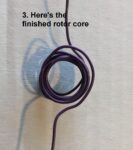
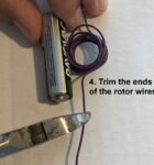
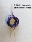
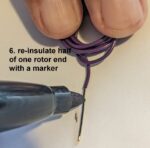
The rotor is a coil of wire with two free ends that have been stripped to bare metal (use a knife or side-cutters carefully) so that the ends make electrical contact in a manner seen below. Key thing: Lay the coil flat and insulate one side of the bare wire by rubbing a good marker on it. This makes sure that the current gets interrupted on part of the cycle and keeps the rotor going in one direction.
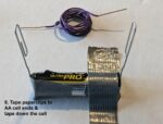
Use a simple AA dry cell as the current source. Take two bare-metal paper clips (that it, not plastic-coated) and straighten out a length on each to make a vertical support for the rotor, as below. Affix the paper clips to the battery, one on each end, so that they stand vertically. Stiff duct tape should work. Brace the AA cell against rolling, such as with lumps of clay:
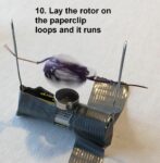
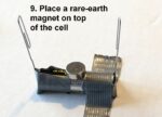
Now put a strong rare-earth magnet on top of the AA cell. Slide the rotor into position between the paper clip ends, and bend one or both ends to keep the rotor from slipping out. The rotor should start spinning vigorously, perhaps needing an initial spin by hand!
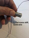
Hints: Make the rotor with wire that’s stiff but not too heavy. Use only solid wire, not stranded wire, which goes limp.
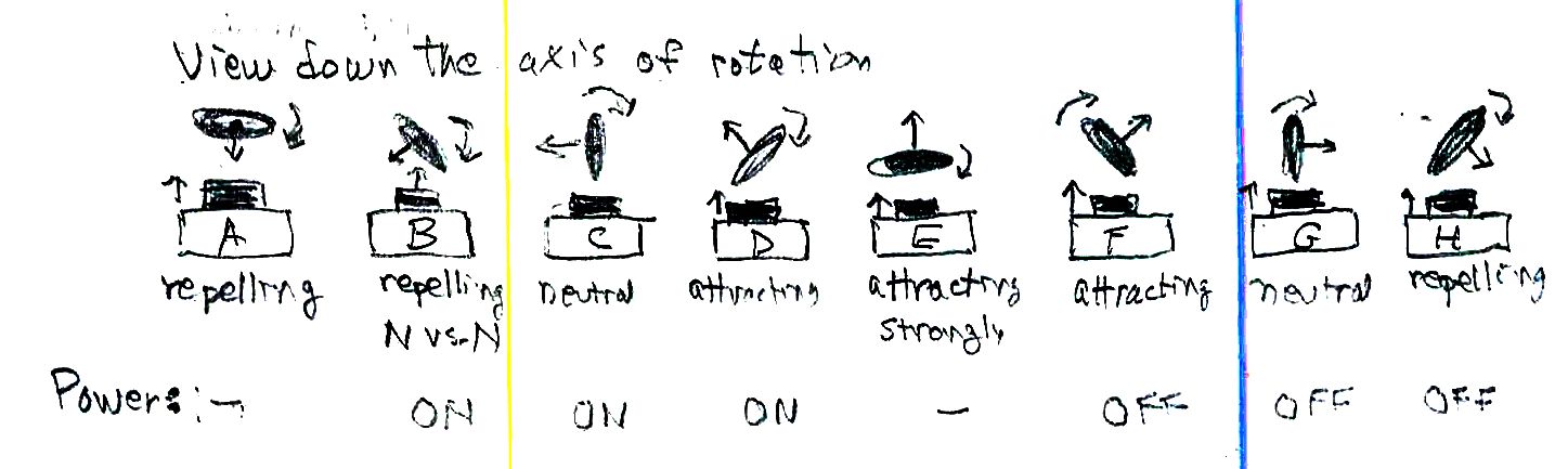
How it works: As the rotor rotates over the magnet, it is at times attracted to the magnet and at times repelled. The diagram below shows eight phases of a complete rotation as we look down the axis of the rotor. At point A there’s a repulsion of the rotor as an electromagnet but no torque or twisting action. The rotor will keep moving, however, if it has been rotating; it has momentum (angular momentum). At point B the rotor and the fixed magnet repel each other, forcing the rotor to rotate faster. At point C the effect is neutral but the rotor has angular momentum to keep rotating. At point D the fixed magnet “sees” the opposite pole of the rotor and attracts it, helping to pull the rotor around further. At later points F, G, H we want the current off so that the rotor is not pulled the opposite way to bring it ultimately to a standstill. To do this we have put the insulating marker coating on one side (say, up to one half) of the circumference of the bare wire end.
Here’s how the motor is assembled. The images below are numbered; the numbers and the text only show when you click an image to see it full size (a quirk of WordPress)


You can go further with this demo, making it more of an experiment. You can find the magnetic polarity (north and south directionality) of both the fixed magnet and the rotor. Use a simple compass to see which end of the compass needle moves toward the rotor (energized but held from rotating) or the fixed magnet. The rotor’s polarity depends on the direction of the current (you can swap it end for end to change the direction of rotation). Its polarity also depends on which way you wrapped the rotor, clockwise of counterclockwise as viewed from the end; you can even predict the polarity from the “right-hand rule” relating current and the magnetic field (look this up). The direction should depend on the polarity of the fixed magnet, too; flip it over and watch again.